
#include <stdio.h>
#include "platform.h"
#include "xil_printf.h"
#include "xparameters.h"
#include "xgpio.h"
#include "sleep.h"

#define CHANNEL_1	1
#define OUTPUT		0

XGpio GPIO_LED;

int main()
{
    init_platform();

    XGpio_Initialize(&GPIO_LED, XPAR_AXI_GPIO_0_DEVICE_ID);		// 초기화
    XGpio_SetDataDirection(&GPIO_LED, CHANNEL_1, OUTPUT); 		// 방향 설정

    print("Hello World\n\r");
    print("Successfully ran Hello World application\n\r");

    while (1)
    {
    	XGpio_DiscreteWrite(&GPIO_LED, CHANNEL_1, 0x00);
    	usleep(1000000);
    	//XGpio_DiscreteWrite(&GPIO_LED, CHANNEL_1, 0xff);
    	usleep(1000000);
    }

    cleanup_platform();
    return 0;
}xparameters.h 파일에 memory map 과 같은 기본 설정 내용들이 들어가 있습니다.
xgpio.h는 gpio를 사용하기 위한 기본 함수들이 포함되어 있습니다.
XGpio는 구조체입니다.
typedef struct {
	UINTPTR BaseAddress;	/* Device base address */
	u32 IsReady;		/* Device is initialized and ready */
	int InterruptPresent;	/* Are interrupts supported in h/w */
	int IsDual;		/* Are 2 channels supported in h/w */
} XGpio;XGpio 구조체로 선언된 GPIO_LED 변수의 정보 설정을 합니다.
GPIO 포트 방향을 아래와 같이 설정합니다.
메모리 주소로 LED제어
해당 메모리 주소를 알고 있으면 레지스터를 접근해서 설정 및 read, write를 할 수 있습니다.
#include <stdio.h>
#include "platform.h"
#include "xil_printf.h"
#include "xparameters.h"
#include "xgpio.h"
#include "sleep.h"

#define CHANNEL_1	1
#define OUTPUT		0

XGpio GPIO_LED;

int main()
{
    init_platform();

    XGpio_Initialize(&GPIO_LED, XPAR_AXI_GPIO_0_DEVICE_ID);		// 초기화
    XGpio_SetDataDirection(&GPIO_LED, CHANNEL_1, OUTPUT); 		// 방향 설정

    print("Hello World\n\r");
    print("Successfully ran Hello World application\n\r");

    *(volatile uint32_t *)(0x40000000+4) = 0x00; // input output 선언 (output)

    while (1)
    {
    	//XGpio_DiscreteWrite(&GPIO_LED, CHANNEL_1, 0x00);
    	*(volatile uint32_t *)0x40000000 |= 0x00;		// (자로형*)포인터 주소 // *(자로형*)포인터 주소 : 주소 안에다 넣기
    	usleep(1000000);
    	//XGpio_DiscreteWrite(&GPIO_LED, CHANNEL_1, 0xff);
    	*(volatile uint32_t *)0x40000000 |= 0xff;		// 0x40000000 주소에 찾아가서 0xff을 입력시켜라
    	usleep(1000000);
    }
    cleanup_platform();
    return 0;
}
0x40000000 번지가 GPIO BASE 주소 입니다(1편 참조). 그리고 GPIO BASE 주소부터 레지스터가 있습니다.
주소에 대응하는 레지스터는 Xilinx GPIO IP 문서파일을 확인해보면 아래와 같이 설명이 되어있습니다.
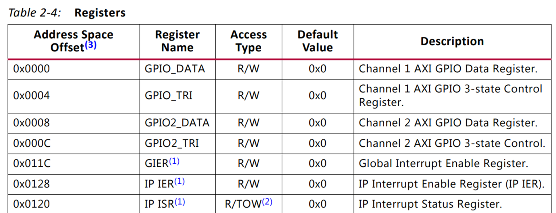
BASE Address + 0x0000는 GPIO Data 레지스터입니다.
BASE Address + 0x0004는 GPIO 의 방향을 설정하는 Control 레지스터입니다.
DDR_LED = 0x00 아래 코드의 뜻은 *(volatile *u32)(0x40000000 + 0x0004) = 0x00 입니다.
"0x40000004 주소가 가리키는 곳에 0x00값을 넣는다" 입니다.
다시 해석하면 GPIO Channel 1의 포트 방향 레지스터 설정 값은 0x00 이다.
"GPIO Channel1의 포트는 output이다" 입니다.
Block Design

코드
GitHub - kyw6416/FPGA_MicroBlaze_Led
Contribute to kyw6416/FPGA_MicroBlaze_Led development by creating an account on GitHub.
github.com
동작영상