
반응형
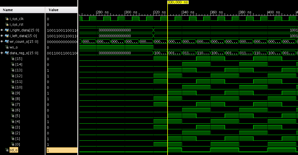
'sd_o'는 들어오는 데이터 'data_reg_o[DATA_WIDTH - 1]'의 최상위 비트(MSB) 값을 사용
//Parallel to serial conversion of incoming data
always @ (negedge i_sys_clk or posedge i_sys_rst) begin
    if(i_sys_rst) begin
        sd_o <= 1'b0;
    end else begin
        sd_o <= data_reg_o[DATA_WIDTH -1];
    end
end
ShiftReg.v
module ShiftReg#(
    parameter DATA_WIDTH=16
) (
    input i_sys_clk,
    input i_sys_rst,
    input [DATA_WIDTH-1:0] i_right_data,
    input [DATA_WIDTH-1:0] i_left_data,

    output reg [DATA_WIDTH-1:0] wr_count_o,
    output reg ws_o,
    output reg [DATA_WIDTH-1:0] data_reg_o,
    output reg sd_o
);

//Count the number of bits to be transmitted
//It has to be same as the data width
always @ (negedge i_sys_clk or posedge i_sys_rst) begin
    if(i_sys_rst) begin
        wr_count_o <= DATA_WIDTH[1'b0];
    end else begin
        if(wr_count_o == DATA_WIDTH - 1) begin
            wr_count_o <= DATA_WIDTH[1'b0];
        end else begin
            wr_count_o <= wr_count_o + 1;
        end
    end
end

always @ (negedge i_sys_clk or posedge i_sys_rst) begin
    if(i_sys_rst) begin
        ws_o <= 1'b0;
    end else begin
        if(wr_count_o == DATA_WIDTH - 1) begin
            ws_o <= ~ws_o;
        end
    end
end

//Data mux and shift register for left and right channels
//left valid data synchronization with o_WS
always @ (negedge i_sys_clk or posedge i_sys_rst) begin
    if(i_sys_rst) begin
        data_reg_o <= DATA_WIDTH[1'b0];
    end else begin
        if(wr_count_o == DATA_WIDTH - 1 && !ws_o) begin // left channel end
            data_reg_o <= i_right_data;
        end else if(wr_count_o == DATA_WIDTH - 1 && ws_o)begin // right channel end
            data_reg_o <= i_left_data;
        end else begin
            data_reg_o <= {data_reg_o[DATA_WIDTH - 2:0], data_reg_o[DATA_WIDTH-1]};
        end
    end
end

//Parallel to serial conversion of incoming data
always @ (negedge i_sys_clk or posedge i_sys_rst) begin
    if(i_sys_rst) begin
        sd_o <= 1'b0;
    end else begin
        sd_o <= data_reg_o[DATA_WIDTH -1];
    end
end

endmoduleTB
`timescale 1ns/1ps

module ShiftRge_TB();
    reg i_sys_clk;
    reg i_sys_rst;
    reg [15:0] i_right_data;
    reg [15:0] i_left_data;
    wire [15:0] wr_count_o;
    wire ws_o;
    wire [15:0] data_reg_o;
    wire sd_o;

    // Instantiate the SerialData module
    ShiftReg #(
        .DATA_WIDTH(16)
    ) ShiftReg (
        .i_sys_clk(i_sys_clk),
        .i_sys_rst(i_sys_rst),
        .i_right_data(i_right_data),
        .i_left_data(i_left_data),
        .wr_count_o(wr_count_o),
        .ws_o(ws_o),
        .data_reg_o(data_reg_o),
        .sd_o(sd_o)
    );

    // Clock generation
    always begin
        #5 i_sys_clk = ~i_sys_clk;
    end

    // Testbench stimulus
    initial begin
        i_sys_clk = 0;
        i_sys_rst = 1;
        i_right_data = 16'h0000;
        i_left_data = 16'h0000;

        // Reset the module
        #10 i_sys_rst = 0;

        // Observe the output for multiple clock cycles
        #310;

        // Change input data
        i_right_data = 16'b1001100110011001;
        i_left_data = 16'b1001100110011001;

        // Observe the output for multiple clock cycles
        #400;

        // Finish the simulation
        $finish;
    end
endmodulesim
반응형