
BA(bank address)값에 따라 bank가 결정되고, A0 ~ Axx(address)값에 따라 시작 열(Column)의 위치가 선택
A10은 Read/Write 후 Precharge명령을 자동으로 실행할지 결정(Auto Precharge)
Activate 와 Read/Write사이에는 일정 시간(tRCD) 경과해야 한다. AL(Additive Latency)를 사용하여 Read/Write 실행을 AL Clock만큼 지연시켜 tRCD이 경과하기 전에 Read 또는 Write 명령을 내림
READ
WRITE bursts are initiated with a WRITE command. DDR2 SDRAM uses WL equal to RL minus one clock cycle (WL = RL - 1CK) (see READ). The starting column and bank addresses are provided with the WRITE command, and auto precharge is either enabled or disabled for that access. If auto precharge is enabled, the row being accessed is precharged at the completion of the burst.
WRITE burst는 WRITE command으로 시작됩니다. DDR2 SDRAM은 WL(Write Latency)을 RL(Read Latency)에서 한 클럭 사이클을 뺀 값으로 사용합니다 (WL = RL - 1CK) (READ를 참조). starting column과 bank address는 WRITE command과 함께 제공되며, 해당 액세스에 대해 auto precharge가 활성화되거나 비활성화됩니다. auto precharge가 활성화된 경우, 액세스되는 row은 burst가 완료될 때 precharge됩니다.
Note: For the WRITE commands used in the following illustrations, auto precharge is disabled.
참고: 다음의 그림에서 사용된 WRITE 명령들은 자동 프리차지가 비활성화되어 있습니다.
During WRITE bursts, the first valid data-in element will be registered on the first rising edge of DQS following the WRITE command, and subsequent data elements will be registered on successive edges of DQS. The LOW state on DQS between the WRITE command and the first rising edge is known as the write preamble; the LOW state on DQS following the last data-in element is known as the write postamble.
WRITE burst 동안, 첫 번째 유효한 데이터 입력 요소는 WRITE 명령 후의 DQS의 첫 번째 rising edge에서 등록되고, 이후의 데이터 요소들은 DQS의 연속적인 에지에서 등록됩니다. WRITE 명령과 첫 번째 상승 에지 사이의 DQS의 LOW 상태는 write preamble로 알려져 있고, 마지막 데이터 입력 요소 이후의 DQS의 LOW 상태는 write postamble로 알려져 있습니다.
The time between the WRITE command and the first rising DQS edge is WL ±tDQSS. Subsequent DQS positive rising edges are timed, relative to the associated clock edge, as ±tDQSS. tDQSS is specified with a relatively wide range (25% of one clock cycle). All of the WRITE diagrams show the nominal case, and where the two extreme cases (tDQSS[MIN] and tDQSS [MAX]) might not be intuitive, they have also been included. Figure 58 shows the nominal case and the extremes of tDQSS for BL = 4. Upon completion of a burst, assuming no other commands have been initiated, the DQ will remain High-Z and any additional input data will be ignored
WRITE command과 첫 번째 rising DQS 에지 사이의 시간은 WL ± tDQSS 입니다. 이후 DQS의 positive rising 에지들은 관련된 clock edge에 대해 ±tDQSS로 시간이 계산됩니다. tDQSS는 상대적으로 넓은 범위(하나의 클럭 주기의 25%)로 지정됩니다. 모든 WRITE 다이어그램은 정상적인 경우를 보여주며, 두 극단적인 경우(tDQSS[MIN] 및 tDQSS[MAX])가 직관적이지 않을 수 있는 곳에서도 포함되어 있습니다. Figure 58은 BL = 4에 대한 tDQSS의 정상적인 경우와 극단적인 경우를 보여줍니다. burst가 완료된 후에는, 다른 명령이 시작되지 않았다면, DQ는 High-Z 상태를 유지하고 추가적인 입력 데이터는 무시됩니다.

Notes: 1. Subsequent rising DQS signals must align to the clock within tDQSS.
2. DI b = data-in for column b.
3. Three subsequent elements of data-in are applied in the programmed order following DI b.
4. Shown with BL = 4, AL = 0, CL = 3; thus, WL = 2.
5. A10 is LOW with the WRITE command (auto precharge is disabled).
참조
1. 이후에 상승하는 DQS 신호들은 tDQSS 내에서 클럭에 맞춰야 합니다.
2. DI b는 column b에 대한 데이터 입력을 나타냅니다.
3. DI b 뒤에 프로그래밍된 순서로 세 가지 연속적인 데이터 입력 요소가 적용됩니다.
4. BL = 4, AL = 0, CL = 3이므로, WL = 2
5. WRITE command을 내릴 때 A10은 LOW 상태입니다(auto precharge가 비활성화 상태입니다.
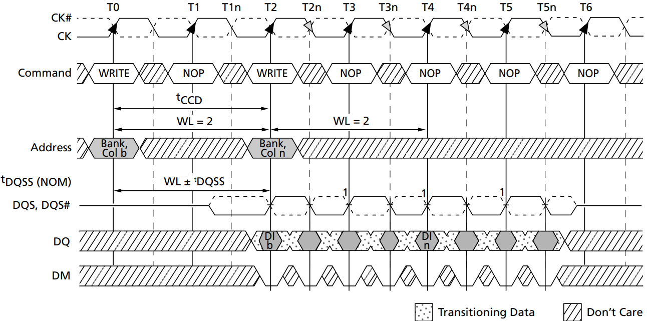
Data for any WRITE burst may be concatenated with a subsequent WRITE command to provide continuous flow of input data. The first data element from the new burst is applied after the last element of a completed burst. The new WRITE command should be issued x cycles after the first WRITE command, where x equals BL/2.
어떤 WRITE burst에 대한 데이터도 consecutive 입력 데이터의 흐름을 제공하기 위해 다음 WRITE command과 연결될 수 있습니다. 새로운 burst에서의 첫 번째 데이터 요소는 완료된 버스트의 마지막 요소 이후에 적용됩니다. 새로운 WRITE command은 첫 번째 WRITE 명령 후에 x cycle이 지난 후에 발행되어야 하며, 여기서 x는 BL/2와 같습니다.
Figure 59 shows concatenated bursts of BL = 4 and how full-speed random write accesses within a page or pages can be performed. An example of nonconsecutive WRITEs is shown in Figure 60. DDR2 SDRAM supports concurrent auto precharge options, as shown in Table 43.
Figure 59는 BL = 4의 연결된 burst를 보여주며, 페이지 또는 여러 페이지 내에서 어떻게 full-speed의 random write accesses가 수행될 수 있는지 보여줍니다. nonconsecutive WRITE의 예시는 Figure 60에서 확인할 수 있습니다. DDR2 SDRAM은 Table 43에 나타난대로 concurrent auto precharge 옵션을 지원합니다.
Notes:
1. Subsequent rising DQS signals must align to the clock within tDQSS.
2. DI b, etc. = data-in for column b, etc.
3. Three subsequent elements of data-in are applied in the programmed order following DI b.
4. Three subsequent elements of data-in are applied in the programmed order following DI n.
5. Shown with BL = 4, AL = 0, CL = 3; thus, WL = 2.
6. Each WRITE command may be to any bank.
참조
1. 이후에 상승하는 DQS 신호들은 tDQSS 내에서 클럭에 맞춰야 합니다.
2. DI b = column b에 대한 데이터 입력
3. DI b 다음에 프로그래밍된 순서대로 세 개의 후속 데이터 입력 요소가 적용됩니다.
4. DI n 다음에 프로그래밍된 순서대로 세 개의 후속 데이터 입력 요소가 적용됩니다.
5. BL = 4, AL = 0, CL = 3으로 표시; 따라서, WL = 2.
6. 각각의 WRITE command는 어느 bank으로도 가능합니다."

Notes:
1. Subsequent rising DQS signals must align to the clock within tDQSS.
2. DI b (or n), etc. = data-in for column b (or column n).
3. Three subsequent elements of data-in are applied in the programmed order following DI b.
4. Three subsequent elements of data-in are applied in the programmed order following DI n.
5. Shown with BL = 4, AL = 0, CL = 3; thus, WL = 2.
6. Each WRITE command may be to any bank.
참조
1. 이후에 상승하는 DQS 신호들은 tDQSS 내에서 클럭에 맞춰야 합니다.
2. DI b (or n) = column b (or column n)에 대한 데이터 입력
3. DI b 다음에 프로그래밍된 순서대로 세 개의 후속 데이터 입력 요소가 적용됩니다.
4. DI n 다음에 프로그래밍된 순서대로 세 개의 후속 데이터 입력 요소가 적용됩니다.
5. BL = 4, AL = 0, CL = 3으로 표시; 따라서, WL = 2.
6. 각각의 WRITE command는 어느 bank으로도 가능합니다."
DDR2 SDRAM does not allow interrupting or truncating any WRITE burst using BL = 4 operation. Once the BL = 4 WRITE command is registered, it must be allowed to complete the entire WRITE burst cycle. However, a WRITE BL = 8 operation (with auto precharge disabled) might be interrupted and truncated only by another WRITE burst as long as the interruption occurs on a 4-bit boundary due to the 4n-prefetch architecture of DDR2 SDRAM. WRITE burst BL = 8 operations may not be interrupted or truncated with any command except another WRITE command, as shown in Figure 61.
DDR2 SDRAM은 BL = 4 작업을 사용하여 어떤 WRITE burst도 중단하거나 잘라내는 것을 허용하지 않습니다. 한번 BL = 4 WRITE command이 등록되면, 전체 WRITE burst 주기를 완료할 수 있도록 허용되어야 합니다. 그러나, WRITE BL = 8 작업(auto precharge가 비활성화된 상태)은 DDR2 SDRAM의 4n-prefetch 아키텍처로 인해 4비트 경계에서만 중단이 발생하는 경우에만 다른 WRITE burst에 의해 중단되거나 잘라낼 수 있습니다. Figure 61에서 보여지는 것처럼, WRITE burst BL = 8 작업은 다른 WRITE 명령 외에는 어떤 명령으로도 중단하거나 잘라낼 수 없습니다.

Notes:
1. BL = 8 required and auto precharge must be disabled (A10 = LOW).
2. The NOP or COMMAND INHIBIT commands are valid. The PRECHARGE command cannot be issued to banks used for WRITEs at T0 and T2.
3. The interrupting WRITE command must be issued exactly 2 × tCK from previous WRITE.
4. The earliest WRITE-to-PRECHARGE timing for WRITE at T0 is WL + BL/2 + tWR where tWR starts with T7 and not T5 (because BL = 8 from MR and not the truncated length).
5. The WRITE command can be issued to any valid bank and row address (WRITE command at T0 and T2 can be either same bank or different bank).
6. Auto precharge can be either enabled (A10 = HIGH) or disabled (A10 = LOW) by the interrupting WRITE command.
7. Subsequent rising DQS signals must align to the clock within tDQSS.
8. Example shown uses AL = 0; CL = 4, BL = 8.
참고
1. BL = 8이 필요하며 auto precharge는 비활성화해야 합니다 (A10 = LOW).
2. NOP 또는 COMMAND INHIBIT command는 유효합니다. PRECHARGE command은 T0와 T2에서 WRITE에 사용된 bank에 발행할 수 없습니다.
3. 중단시키는 WRITE 명령은 이전 WRITE로부터 정확히 2 × tCK 이후에 발행해야 합니다.
4. T0에서의 WRITE에 대한 최초의 WRITE-to-PRECHARGE 타이밍은 WL + BL/2 + tWR로, 여기서 tWR은 T5가 아닌 T7에서 시작합니다 (왜냐하면 BL = 8은 잘라낸 길이가 아니라 MR에서 온 것이기 때문입니다).
5. WRITE 명령은 어떤 유효한 bank과 행 주소에도 발행될 수 있습니다 (T0와 T2에서의 WRITE 명령은 같은 bank이거나 다른 bank가 될 수 있습니다).
6. interrupting WRITE 명령에 의해 auto precharge는 활성화 (A10 = HIGH) 또는 비활성화 (A10 = LOW)될 수 있습니다.
7. 이후의 rising DQS 신호는 tDQSS 내에서 클럭과 일치해야 합니다.
8. 보여진 예시는 AL = 0; CL = 4, BL = 8을 사용합니다.
Data for any WRITE burst may be followed by a subsequent READ command. To follow a WRITE, tWTR should be met, as shown in Figure 62. The number of clock cycles required to meet tWTR is either 2 or tWTR/tCK, whichever is greater. Data for any WRITE burst may be followed by a subsequent PRECHARGE command. tWR must be met, as shown in Figure 63. tWR starts at the end of the data burst, regardless of the data mask condition.
어떤 WRITE burst에 대한 데이터는 이후의 READ command를 따를 수 있습니다. WRITE를 따르려면, Figure 62에 표시된 대로 tWTR이 충족되어야 합니다. tWTR을 충족하기 위해 필요한 Clock cycle 수는 2 또는 tWTR/tCK 중 더 큰 값입니다. 어떤 WRITE burst에 대한 데이터는 이후의 PRECHARGE Command를 따를 수 있습니다. Figure 63에 표시된 대로 tWR이 충족되어야 합니다. tWR은 데이터 마스크 조건에 관계없이 데이터 burst의 끝에서 시작합니다.

Notes:
1. tWTR is required for any READ following a WRITE to the same device, but it is not required between module ranks.
2. Subsequent rising DQS signals must align to the clock within tDQSS.
3. DI b = data-in for column b; DO n = data-out from column n.
4. BL = 4, AL = 0, CL = 3; thus, WL = 2.
5. One subsequent element of data-in is applied in the programmed order following DI b.
6. tWTR is referenced from the first positive CK edge after the last data-in pair.
7. A10 is LOW with the WRITE command (auto precharge is disabled).
8. The number of clock cycles required to meet tWTR is either 2 or tWTR/tCK, whichever is greater.
참고
1. tWTR은 동일한 장치에 대한 WRITE를 따르는 모든 READ에 필요하지만, 모듈 순위(rank) 간에는 필요하지 않습니다.
2. 차후에 발생하는 DQS의 rising 신호는 tDQSS 범위 내에서 clock에 정렬되어야 합니다.
3. DI b = column b에 대한 데이터 입력; DO n = column n에서 출력되는 데이터.
4. BL = 4, AL = 0, CL = 3; 따라서, WL = 2입니다.
5. DI b를 따른 프로그래밍된 순서로 하나의 추가 데이터 입력 요소가 적용됩니다.
6. tWTR은 마지막 데이터 입력 쌍 후의 첫 번째 positive의 CK edge에서 참조됩니다.
7. A10은 WRITE 명령어와 함께 LOW입니다 (auto precharge가 비활성화됨).
8. tWTR을 충족하기 위해 필요한 클럭 사이클 수는 2 또는 tWTR/tCK 중 더 큰 값입니다.
